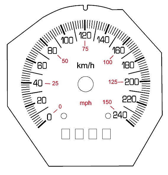
Speedo Face printing (240kph / 150mph) |
Post Reply 
|
Page <1234> |
| Author | ||
Dawg 
Senior Member 

Joined: 15 August 2009 Location: Canada Status: Offline Points: 988 |
 Post Options Post Options
 Quote Reply Quote Reply
 Posted: 06 September 2010 at 7:56pm Posted: 06 September 2010 at 7:56pm |
|
|
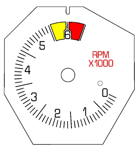
My tach yellows out at 5500 and reds at 6000. It continues on to 6500 although there's no number there.
The Dawg
|
||
|
You dream it up....I'll make it
|
||
 |
||
|
Romeo
Senior Post God 

Joined: 16 November 2008 Location: Canada Status: Offline Points: 3033 |
Post Options
Quote Reply
Posted: 06 September 2010 at 7:58pm |
|
|
Looks awesome! Definitely stock-looking! Off-topic question, but do you guys have MPH on your speedos? Mine ONLY has KMH.
|
||
|
Never shift into reverse without a back-up plan.
|
||
|
||
|
Capt Fiero
Admin Group

Founding Member Joined: 12 February 2007 Location: Canada Status: Offline Points: 4039 |
Post Options
Quote Reply
Posted: 06 September 2010 at 10:38pm |
|
|
I would if you could add something "custom" to it, are these faces going to be made in batches or by order? If they were made in batches you could do some sort of Generic thing like "Fiero SS" I know that is a Chevy thing, or just plain "Fiero" but in a different font. Now if they were on a piece by piece basis, maybe 857 Cadero for mine or Cadero for all the Cadero owners. Maybe even just a Fiero Logo someplace on the face. P.S. also the another option is leave the 240 numbering and simply tweak your little signal output to read 240mph for the US guys wanting a "show piece" for there car. Archie might buy a few from you just to stock them with his kits. P.P.S Whoever asked earlier, yes the later CDN Metric speedo's have MPH on the inside, same with the USA version they got Metric on the inside. When I first brought my 85GT to Canada it was a US 85MPH speedo without the Metric so I had to get real good quickly with doing the math in my head. |
||
|
Capt Fiero
88 Fiero GT 5spd V6 Eight Fifty Seven GT V8 5spd. |
||
|
||
|
Capt Fiero
Admin Group
Founding Member Joined: 12 February 2007 Location: Canada Status: Offline Points: 4039 |
Post Options
Quote Reply
Posted: 06 September 2010 at 10:39pm |
|
|
Oh did you ever think of a white face option? I have a white face guage set (Volts and Oil Pressure) here and would love to have a matching speedo for it. I can offer it up for you to copy and add to your stock of images. |
||
|
Capt Fiero
88 Fiero GT 5spd V6 Eight Fifty Seven GT V8 5spd. |
||
|
||
|
Dawg
Senior Member
Joined: 15 August 2009 Location: Canada Status: Offline Points: 988 |
Post Options
Quote Reply
Posted: 07 September 2010 at 9:49am |
|
|
I'm more interested in recreating the factory look at the moment. Not that I wouldn't want something different in my cluster, but I need to try and keep the price down to generate some sales volume.
Creating a standard look that I can run off by the dozens saves time and effort. So then, what look to choose you say? Good question. I'm reasoning that no one can complain too much if I offer the factory look. Many could, however, not like some aspect of a more custom arrangement. This would complicate things. Feel free to send me ideas though. After all, what is "factory looking" anyway? Additionally, there should be something there that shows it's my design. May as well be something cool. Oh and why don't you upload a pic of your white gauges so I can get a feel for what you're wanting. Cheers, The Dawg |
||
|
You dream it up....I'll make it
|
||
|
||
|
Romeo
Senior Post God
Joined: 16 November 2008 Location: Canada Status: Offline Points: 3033 |
Post Options
Quote Reply
Posted: 07 September 2010 at 2:36pm |
|
Yes actually, upon going out and looking at my car that night I realized I have the same thing, although fuel cut-off occurs at 6250RPM. I also like having the numbers. lol |
||
|
Never shift into reverse without a back-up plan.
|
||
|
||
|
CFoss
Senior Member

Joined: 13 February 2007 Location: Canada Status: Offline Points: 580 |
Post Options
Quote Reply
Posted: 13 September 2010 at 9:22am |
|
|
Hey all, haven't been around for a while, but I have some input on this....
I did a bit of research on the speedo back a while. From what I remember it's a stepper motor drive circuit which accepts the 4000ppm and converts it to deflection.
This means it would be way simpler to modify the input signal than the internals of the speedo. The speedo buffer drives the speedo itself and the ecm, so fix the input signal, and the ecm sees the right speed as well.
So, we need a circuit which can read a frequency, multiply it by a factor which is externally adjustable, then output a new frequency...solution...pic (Programmable integrated controller). It would be an external device requiring power, ground, frequency in and frequency out. Pretty simple hook up. Then, adjust the frequency out with a potentiometer.
There is another way with f to v convertors....run a f to v, then run a v to f which is adjustable. It's simpler and more complex at the same time....less engineering because the ciruits are already worked out for you, but higher parts count means building them is harder and more costly. The device name is LM331N.
If anyone wants to experiment I have a bunch here and could mail them off.
Chay |
||
|
86 SE 3.4
|
||
|
||
|
Dawg
Senior Member
Joined: 15 August 2009 Location: Canada Status: Offline Points: 988 |
Post Options
Quote Reply
Posted: 13 September 2010 at 10:45pm |
|
|
The VSS signal can not be converted externally. This will not be a plug in kit.
The speedo is the last to get this signal. It's the furthest from the plug. First thing to happen is the sine wave gets converted to square and divided in half for the ECM. Then the signal goes to the stepper driven odometer and trip meter. Lastly the signal is sent to the speedo. The speedo needle is not a stepper or a regular analog meter. I think it's called an air core meter. It's totally digital however. If the VSS signal is altered at the plug, it will bugger up everything except the speedo. The pc board will have to be altered to do this right. I have an engineer friend of mine working on the code. When I get back from holidays, him and I will dig into this more seriously. The first "PIC" will have a fixed ratio. I will test my theories with it. Then the adjustible one will be built. If all goes well, I should have some news in 3 weeks or so. But hey, If anyone wants to give it a try, go for it. The Dawg |
||
|
You dream it up....I'll make it
|
||
|
||
|
Duck
Newbie 

Never fear, Superduck is here! Joined: 13 February 2007 Location: Canada Status: Offline Points: 40 |
Post Options
Quote Reply
Posted: 13 September 2010 at 11:38pm |
|
|
I'm still confused why you guys are spending so much time when an XTAL just needs to be replaced. If I remember correctly, I found the right crystal available. I'm pretty sure if someone needed a different speedo (it took me a lot to come up with that magic 240km/h number), it wouldn't be too hard to find a different crystal, rather than going with some custom programming etc. Whatever floats your boat though. Cheers, Kris |
||
|
How much horsepower can I have and still go to heaven?
|
||
|
||
|
Dawg
Senior Member
Joined: 15 August 2009 Location: Canada Status: Offline Points: 988 |
Post Options
Quote Reply
Posted: 14 September 2010 at 8:16am |
|
|
There are several reasons why the crystal method isn't the greatest. There is a thread on Pennocks right now with ALL the details. But the main reason is that not all the speedos have the same crystal. The circuit changed over the years. There's at least 4 different versions.
This unit will work for any speedo. The Dawg. |
||
|
You dream it up....I'll make it
|
||
|
||
|
CFoss
Senior Member
Joined: 13 February 2007 Location: Canada Status: Offline Points: 580 |
Post Options
Quote Reply
Posted: 14 September 2010 at 8:45am |
|
|
I apologize...air core meter is entirely correct. Still, it has a driver which I found difficult to engineer a variable element in.
Modifying the external signal...if your intention is to change the ful scale deflection of the meter I guess you are right. The ecm would end up seeing a lower value than is correct, because the buffer output gets modified. One easy way I found is to run an external buffer, like all the other cars did from this era...basically they took the buffer out of the speedo and had it externally done. It's a little yellow plastic box, with a couple of transistor buffers in it. I had a couple for my 3.4 swap, and of course I ended up not needing them. So, you could build a box which takes in power, ground, vss, and outputs buffered speed to the ecm, modified speed to the speedo.
This has to be easier than trying to fit something in the speedo/modifying the air core driver.
Also, it's plug and play and if the speedo dies, just plug in another one. The odometer would still need the corect signal...the fly in the ointment. I don't think it would be too bad though...cut a trace and insert the correct signal. Too bad it runs from this though. This is kinda why I was looking into the digital cluster from the Cavi. Overall it may actually be less hassle...not stock though and they are hard to find now for some reason. Chay |
||
|
86 SE 3.4
|
||
|
||
|
Dr.Fiero
Senior Post God
Joined: 12 February 2007 Location: Canada Status: Offline Points: 1726 |
Post Options
Quote Reply
Posted: 14 September 2010 at 10:07am |
|
|
Just in attempt to not re-invent the wheel here....
Has anyone looked at/into the DRAC modules used in the S10's etc from the late 80's early 90's (and possibly others)?? The Digital Ratio Adapter Controller was used to change the input to the speedo/odometer/cruise control, since there was such a wide variation of trannies, and rear end ratios. It has a bunch of soldered jumpers in it that have already been hacked, and decoded. |
||
|
||
|
Dawg
Senior Member
Joined: 15 August 2009 Location: Canada Status: Offline Points: 988 |
Post Options
Quote Reply
Posted: 19 September 2010 at 2:27pm |
|
|
I haven't seen that one John but I did find something like it. The problem is pricing. The one I was looking at was for motorcycles. It was $120.
I'd like to find a total solution for something like $80. You send my your speedo, I do all the mods and send it back. So programming my own chips is in order I think. The Dawg.....enjoying his holiday! |
||
|
You dream it up....I'll make it
|
||
|
||
|
Dawg
Senior Member
Joined: 15 August 2009 Location: Canada Status: Offline Points: 988 |
Post Options
Quote Reply
Posted: 03 October 2010 at 11:55pm |
|
|
Here's some more ideas. White background versions. I like them!
  Something a little different I might try at some point. Dave lent me a gauge cluster so I can try different faces to see how they look when back lit. The Dawg |
||
|
You dream it up....I'll make it
|
||
|
||
|
Duck
Newbie
Never fear, Superduck is here! Joined: 13 February 2007 Location: Canada Status: Offline Points: 40 |
Post Options
Quote Reply
Posted: 04 October 2010 at 9:24am |
|
|
Yea, this is what started my obsession in the first place. The only problem is you can't really have the entire white face light up unless you're going to use some sort of EL panel or something. It's way too patchy so it'll have bright spots. Plus, I find the white faces distracting. The factory-style white face gauges only light up the numbers and lines like the factory Fiero gauges. It'd require several layers to get it working properly.
|
||
|
How much horsepower can I have and still go to heaven?
|
||
|
||
|
Dawg
Senior Member
Joined: 15 August 2009 Location: Canada Status: Offline Points: 988 |
Post Options
Quote Reply
Posted: 04 October 2010 at 11:17am |
|
|
Yes I was planning on letting the whole face light up. I was just going to find a very high quality tracing paper to print on. You're right though, the effect might not turn out so good after all.
As for making the white face opaque and letting light through the graphics, it would surely mean layering. Maybe white on top and black underneath to block the light? It's going to take many hours of experimenting to get any of these faces looking perfect. On a side note, I've ordered the microprocessors and the development kit for the calibration circuit. My buddy is ready to come over and design this with me. We've done many high tech projects together in the past. Film industry props to be exact. On a purely technical level, this will be a walk in the park. I think we'll be pretty close to our target price too. So win win for all I think. It could be another month before I'm actually prepared to mod anyone's gauges. We'll see. Anyone itching to be the first local customer? The Dawg |
||
|
You dream it up....I'll make it
|
||
|
||
|
Duck
Newbie
Never fear, Superduck is here! Joined: 13 February 2007 Location: Canada Status: Offline Points: 40 |
Post Options
Quote Reply
Posted: 04 October 2010 at 11:49am |
|
|
When I originally did it, I had some somewhat translucent white plastic sheets I tried printing onto. They looked great with the backlight off. I didn't really think it through though, so when I turned on the backlight at night, there were bright and dark blotches all over. So, once I dissected the gauge face, I realized how they do it in other cars. Without backlight on, they're white faced with black-ish numbers. When the backlight lights up, just the numbers light up. The factory fiero gauge face is made up of two layers. The top layer is the black with white numbers. The bottom layer is like the top layer, except larger blotchier numbers and lines, in the reddish orange colour. That way you see the white numbers, but the backlight goes through the red layer causing them to light up red/orange. You'd then need another layer on top, of opaque white with translucent numbers and lines. It's not impossible, but you'd either need to be able to print white, or use pure white plastic or something. And you'd basically have to cut out the numbers and stuff, which would be way harder. Unfortunately, you can't just print white with a regular inkjet. Why don't printers have white ink, dammit. (I know) :) And yea, like I said, I've spent a lot of hours planning this out. A printing company is the only real hope of making a professional-looking white face. I'd just stick with black if you're doing it home-made. MUCH easier. Also, try holding a flashlight up to your printed faces and see if the face blocks out all the light. Otherwise you'll get patches too. If there's anything else I can help with, give me a shout. Kris
|
||
|
How much horsepower can I have and still go to heaven?
|
||
|
||
|
Dawg
Senior Member
Joined: 15 August 2009 Location: Canada Status: Offline Points: 988 |
Post Options
Quote Reply
Posted: 07 October 2010 at 1:46pm |
|
|
Thanks Kris.
The Dawg
|
||
|
You dream it up....I'll make it
|
||
|
||
|
Dawg
Senior Member
Joined: 15 August 2009 Location: Canada Status: Offline Points: 988 |
Post Options
Quote Reply
Posted: 07 October 2010 at 1:48pm |
|
|
Update.
The development kit arrived yesterday and all the other bits and pieces needed to get the prototype done. I ordered a couple different chips to try out. We are doing all we can to keep this simple. Making things complicated is easy....  I've sent an email to Jeric with all the parameters and he's coding away. I should have the first circuit breadboarded some time next week. If all goes well with the testing, I'll then concentrate on perfecting the gauge faces. The Dawg |
||
|
You dream it up....I'll make it
|
||
|
||
|
Capt Fiero
Admin Group
Founding Member Joined: 12 February 2007 Location: Canada Status: Offline Points: 4039 |
Post Options
Quote Reply
Posted: 10 October 2010 at 11:22pm |
|
|
I can't wait to be a test mule for this kit.
|
||
|
Capt Fiero
88 Fiero GT 5spd V6 Eight Fifty Seven GT V8 5spd. |
||
|
||
|
Post Reply
|
Page <1234> |
 Tweet
Tweet
|
| Forum Jump | Forum Permissions You cannot post new topics in this forum You cannot reply to topics in this forum You cannot delete your posts in this forum You cannot edit your posts in this forum You cannot create polls in this forum You cannot vote in polls in this forum |


")


 Topic Options
 Romeo wrote: