The ultimate ignition system |
Post Reply 
|
Page <1234> |
| Author | ||
Dawg 
Senior Member 

Joined: 15 August 2009 Location: Canada Status: Offline Points: 988 |
 Post Options Post Options
 Quote Reply Quote Reply
 Posted: 25 November 2009 at 4:41am Posted: 25 November 2009 at 4:41am |
|
|
In my humble opinion, if you're going to try and relocate, you're better off going to a different system all together. If you move this ignition unit, you'll need to mount it on a heat sink anyway, so why not leave it where it is.
As for the magnets, yes, rare earth magnets inside steel cups pointing downwards. Next one will have a custom enclosure machined for the magnets. This will make them easier to mount. And yes, more magnetism, more signal from the pickup sensor. Rare earth magnets last a LONG time too. DG |
||
|
You dream it up....I'll make it
|
||
 |
||
|
Matt
Senior Member

Joined: 09 February 2008 Location: Canada Status: Offline Points: 448 |
Post Options
Quote Reply
Posted: 25 November 2009 at 1:18pm |
|
I suppose if you relocated it, it might give you more room to mount a fan or workout some other method of cooling the heat sink. Maybe a PC CPU water cooling system mounted to the module?  |
||
|
I wanna go fast.
|
||
|
||
|
Patrick
Newbie 
Joined: 19 April 2008 Location: Vancouver Status: Offline Points: 5 |
Post Options
Quote Reply
Posted: 25 November 2009 at 3:14pm |
|
|
Is the relative position of the magnets on the head of the distributor shaft important? If so, how do you know exactly where to place them?
|
||
|
||
|
Patrick
Newbie
Joined: 19 April 2008 Location: Vancouver Status: Offline Points: 5 |
Post Options
Quote Reply
Posted: 25 November 2009 at 3:23pm |
|
|
Dave, I wish you hadn't closed the other thread. I think it's great that there's something/anything being discussed that's generating a little more traffic than usual around here. That's a good thing!
|
||
|
||
|
Capt Fiero
Admin Group 

Founding Member Joined: 12 February 2007 Location: Canada Status: Offline Points: 4039 |
Post Options
Quote Reply
Posted: 25 November 2009 at 3:30pm |
|
|
Ok If you honestly feel that both are actually justified, I have re-opened it. |
||
|
Capt Fiero
88 Fiero GT 5spd V6 Eight Fifty Seven GT V8 5spd. |
||
|
||
|
Patrick
Newbie
Joined: 19 April 2008 Location: Vancouver Status: Offline Points: 5 |
Post Options
Quote Reply
Posted: 25 November 2009 at 3:36pm |
|
|
Thanks Dave. No doubt both threads will peter out on their own shortly, but it's nice that they can both now die a natural death.
|
||
|
||
|
Dawg
Senior Member
Joined: 15 August 2009 Location: Canada Status: Offline Points: 988 |
Post Options
Quote Reply
Posted: 25 November 2009 at 5:41pm |
|
|
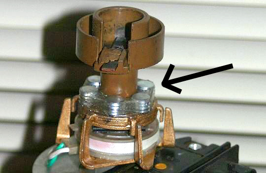
The magnets need to be as balanced as possible. Don't forget, the shaft turns at half the engine RPM. So 6000 RPM means the shaft will be at 3000 RPM. We're getting into a range where an imbalance will either cause vibration that will destroy the bushing over time or cause the magnets themselves to fly off and explode the cap and rotor.
All nasty stuff which is why I'm designing a custom housing that will prevent such things. For the prototype I was very careful how I placed the individual magnets. I also wrapped a wire around them to make sure they stayed put. Lots of epoxy to hold it all together. DG |
||
|
You dream it up....I'll make it
|
||
|
||
|
Dr.Fiero
Senior Post God

Joined: 12 February 2007 Location: Canada Status: Offline Points: 1726 |
Post Options
Quote Reply
Posted: 25 November 2009 at 6:00pm |
|
|
What about from a magnetic polarity point of view?
|
||
|
||
|
Patrick
Newbie
Joined: 19 April 2008 Location: Vancouver Status: Offline Points: 5 |
Post Options
Quote Reply
Posted: 25 November 2009 at 6:56pm |
|
|
I don't think you actually addressed my questions. Trade secret?
|
||
|
||
|
Dawg
Senior Member
Joined: 15 August 2009 Location: Canada Status: Offline Points: 988 |
Post Options
Quote Reply
Posted: 25 November 2009 at 9:54pm |
|
|
Ummm....Well basically, balanced means equal spacing between them. Fit as many magnets on there as you can and make sure if you were to cut the rotor in half, there would be the same number of magnets on one side as the other.
Is that clearer? As for polarity, I found it does matter. It is trial and error however. I take a reading with the magnets one way, then flip them around and test it again. Once I know the polarity, I take them off carefully and stack them all on top of each other and then stick them to a piece of steel. This makes sure I don't lose track of which way is up. DG |
||
|
You dream it up....I'll make it
|
||
|
||
|
CFoss
Senior Member

Joined: 13 February 2007 Location: Canada Status: Offline Points: 580 |
Post Options
Quote Reply
Posted: 25 November 2009 at 10:23pm |
|
|
If the signal from the reluctor can be improved then remoting becomes easier with the improved signal to noise ratio that would result. Just build a box, extend the connector leads, and heat sink away. Something to try one day I guess. Maybe with a spare dist.
I wonder if a MOV might be too slow to effectively damp the coil spike. I suspect the MSD has less inductance and is flowing more current and thus the greater kickback. I built a push pull dc-dc switcher with a 20khz switch frequency and the only thing fast enough to damp the primary spikes was a R-C snubber. Also, the R got hot, as there was a fair amount of energy dissipated (1-2W). I suspect if the MOV works it will get worm in short order, depending on the joule rating. What kid of scope do you have? Fluke scopemeter?? They aren't great at capturing small duration peaks. If you can get one, the portable teks are great. They have a peak detect mode that kicks ass (geek alert). Chay |
||
|
86 SE 3.4
|
||
|
||
|
CFoss
Senior Member
Joined: 13 February 2007 Location: Canada Status: Offline Points: 580 |
Post Options
Quote Reply
Posted: 25 November 2009 at 10:27pm |
|
|
I looked at your other thread, 1.8V, approx sinusoid = 2.5V peak...not too shabby. It should hold up pretty well for remoting I'd guess.
Time to run a bunch of wire around the engine bay and see how much crap it picks up with the scope. C |
||
|
86 SE 3.4
|
||
|
||
|
Patrick
Newbie
Joined: 19 April 2008 Location: Vancouver Status: Offline Points: 5 |
Post Options
Quote Reply
Posted: 25 November 2009 at 10:42pm |
|
|
Ummm... not really. I'm not sure why this is so difficult to get across. Okay, once more... There's six poles (for lack of a better term) on the head of the distributor shaft. What determines where the magnets sit in relation to the poles? If you were to shift them all over an eighth of an inch for example, would that throw it all out of whack. (non-geek alert) Is my question any clearer?
|
||
|
||
|
Dawg
Senior Member
Joined: 15 August 2009 Location: Canada Status: Offline Points: 988 |
Post Options
Quote Reply
Posted: 25 November 2009 at 11:12pm |
|
|
There's six poles (for lack of a better term) on the head of the distributor shaft. What determines where the magnets sit in relation to the poles? That's a better question. I get it. Simple answer, doesn't matter. You're magnetizing the flat piece of metal they're sitting on. Ideally, the rotor is channeling all the magnetism to the poles (fingers). Happy now?.....:) I suspect if the MOV works it will get worm in short order, depending on the joule rating. You can buy some pretty big MOV's these days. We'll see. What kid of scope do you have? Fluke scopemeter?? They aren't great at capturing small duration peaks. If you can get one, the portable teks are great. They have a peak detect mode that kicks ass (geek alert). Yup, Fluke Scopemeter. The scope display is rather slow yes but you can sometimes catch stuff in over sample mode. Also, the DMM's Min/Max feature seems to be much faster. I hope the dissipated energy in the MOV will be reasonable. Time will tell. I will be testing as I go. I have an analog scope in storage I can get if need be. DG |
||
|
You dream it up....I'll make it
|
||
|
||
|
Patrick
Newbie
Joined: 19 April 2008 Location: Vancouver Status: Offline Points: 5 |
Post Options
Quote Reply
Posted: 25 November 2009 at 11:35pm |
|
|
Getting there. So it doesn't matter where the rare earth magnets sit in relation to the existing magnets in the head of the distributor shaft? Or do the rare earth magnets attract/repel themselves into the optimum position? ie... 12, 2, 4, 6, 8, 10 o'clock looking down on the top of the distributor shaft head as opposed to 1, 3, 5, 7, 9, 11 o'clock.
|
||
|
||
|
Dawg
Senior Member
Joined: 15 August 2009 Location: Canada Status: Offline Points: 988 |
Post Options
Quote Reply
Posted: 26 November 2009 at 9:22am |
|
|
Patrick, I understand your question buddy and no, in this case it does not matter. Everything that matters has been revealed. The metal plate acts like a "sponge" if you like, and directs the energy where it's needed.
DG |
||
|
You dream it up....I'll make it
|
||
|
||
|
Patrick
Newbie
Joined: 19 April 2008 Location: Vancouver Status: Offline Points: 5 |
Post Options
Quote Reply
Posted: 26 November 2009 at 9:31am |
|
|
Interesting. Thanks very much for the info, Damien.
|
||
|
||
|
CFoss
Senior Member
Joined: 13 February 2007 Location: Canada Status: Offline Points: 580 |
Post Options
Quote Reply
Posted: 26 November 2009 at 10:25am |
|
|
From the Megasquirt website:
GM and most other electronic spark driven reluctor electronics trigger on the negative going zero transition after a positive voltage. While they could trigger on the rise that is not how they were designed. Thus polarity of the reluctor signal is critical to proper function. In the GM 7/8-pin HEI, the module converts the AC signal from the variable reluctor pick-up {on pins P & N} in the distributor to a 'square wave' tach signal {on pin R} suitable for MegaSquirt-II. Be sure to get the variable reluctor pick-up wires connected properly. Reversing the variable reluctor sensor wires and thus the polarity of the sensor causes the leading voltage to go negative first and the electronics ignores the positive going transition. Thus trigger signal, if ever recognized, is the falling edge of the voltage as the end of the tooth passes. The only way to get proper triggering at the center of the tooth is to have the positive � cycle first (tooth approaching) and the negative � cycle last.
So, from this I get that the polarity is critical as DAWG already noted, amplitude is not so important, and the 0 transition should be as clean as possible (Crosses 0 once, not multiple times). If we can acheive this, then remoting is a good posibility. A 0 crossing detector is a good choice to limit interference, which is probably why they used it.
Chay |
||
|
86 SE 3.4
|
||
|
||
|
Dawg
Senior Member
Joined: 15 August 2009 Location: Canada Status: Offline Points: 988 |
Post Options
Quote Reply
Posted: 26 November 2009 at 4:37pm |
|
|
As a thank you for Dave lending me his distributor I decided to spiffy it up a little. Good thing I did. The clip holding the pickup coil was only holding on with one side and the upper bushing was basically dry. All fixed and lubed now.
See how the shaft was actually scored 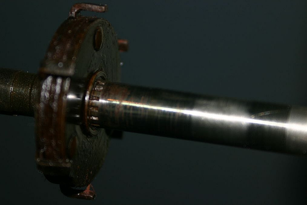 All better now 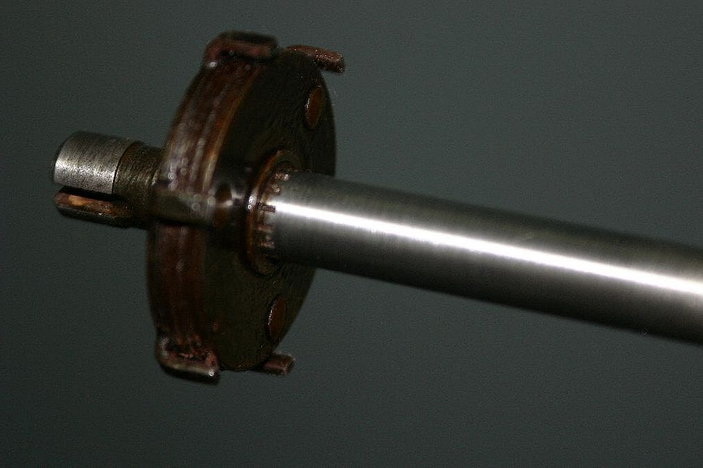 Looking real nice and ready for action 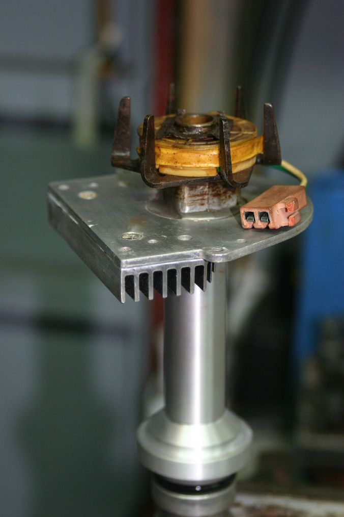 A nice distributor for sure! DG |
||
|
You dream it up....I'll make it
|
||
|
||
|
Capt Fiero
Admin Group
Founding Member Joined: 12 February 2007 Location: Canada Status: Offline Points: 4039 |
Post Options
Quote Reply
Posted: 26 November 2009 at 8:11pm |
|
|
Many Thank You's for setting that up. I should be able to get it back installed in the 88 tomorrow and test fire. Will be nice to be able to fire the car up again.
|
||
|
Capt Fiero
88 Fiero GT 5spd V6 Eight Fifty Seven GT V8 5spd. |
||
|
||
|
Post Reply
|
Page <1234> |
 Tweet
Tweet
|
| Forum Jump | Forum Permissions You cannot post new topics in this forum You cannot reply to topics in this forum You cannot delete your posts in this forum You cannot edit your posts in this forum You cannot create polls in this forum You cannot vote in polls in this forum |


 Topic Options
 Dawg wrote:
 There's no reason why a discussion can't take place in two threads on a similar topic. I was hoping to receive a reply from Chay to a question I had asked him there.