The ultimate ignition system |
Post Reply 
|
Page <1234> |
| Author | |
Dawg 
Senior Member 

Joined: 15 August 2009 Location: Canada Status: Offline Points: 988 |
 Post Options Post Options
 Quote Reply Quote Reply
 Posted: 26 November 2009 at 8:46pm Posted: 26 November 2009 at 8:46pm |
|
Well the cleaned up, oiled up, jacked up distributor is in the car and running perfectly. Sure looks good in there too.
After I took the car for a short run I popped the hood open and touched the heat sink. It was nice and hot which means it's conducting well and sucking heat away from the ignition module. Mission accomplished. I should add that I have one of those MSD coils. So lots of heat to deal with. I have no idea how these modules survive normally. I guess many don't for very long. DG |
|
|
You dream it up....I'll make it
|
|
 |
|
|
Dawg
Senior Member
Joined: 15 August 2009 Location: Canada Status: Offline Points: 988 |
Post Options
Quote Reply
Posted: 26 November 2009 at 8:56pm |
|
Some have asked so I will say that I do have enough aluminum to make 6 or 7 heat sinks. I will get them done this week.
Those interested can PM me. I'm thinking maybe $50-60 for the heat sink, new hardware, heat sink compound and a paper template to show you where to drill the holes. I'll install it for you for an additional $20. DG |
|
|
You dream it up....I'll make it
|
|
|
|
|
Capt Fiero
Admin Group 

Founding Member Joined: 12 February 2007 Location: Canada Status: Offline Points: 4039 |
Post Options
Quote Reply
Posted: 01 December 2009 at 12:47pm |
|
SO how is the test mule doing in the wifes car, been able to drive it much? I know she probably won't rev it that high, but have you had a chance to scream the RPMS up for any prolonged sessions? Any chance to get it hot enough for the rad fan to kick on in Traffic? I am sure a lot of interest will be there once people know this is a bonified save your butt item. |
|
|
Capt Fiero
88 Fiero GT 5spd V6 Eight Fifty Seven GT V8 5spd. |
|
|
|
|
Dawg
Senior Member
Joined: 15 August 2009 Location: Canada Status: Offline Points: 988 |
Post Options
Quote Reply
Posted: 01 December 2009 at 7:49pm |
|
Well, I have driven the snawt out or it. Yes a fair bit of 5000-6500 shifting and no problem other than some pinging. Need to see John and get a chip done for this camshaft. I routinely pop the hood and feel the heat sink. It's always about the same temperature no matter how hot the engine is. Our ignition problems are over, simple as that.
|
|
|
You dream it up....I'll make it
|
|
|
|
|
Dawg
Senior Member
Joined: 15 August 2009 Location: Canada Status: Offline Points: 988 |
Post Options
Quote Reply
Posted: 20 December 2009 at 4:37pm |
|
I had some time today to play. I hooked up a full ignition system on the bench and poked around a bit.
For the benefit of the techies on board, have a look at this: Here's the signal coming from the ignition unit to the coil. Just starting everything is cold. 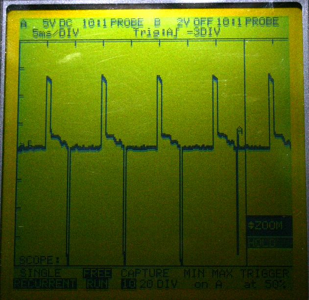 You can see the negative going spikes. Here's a little later. Getting warmer. 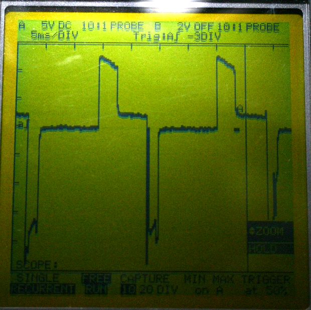 Even hotter now and I've changed the voltage scaling to attempt a better reading. 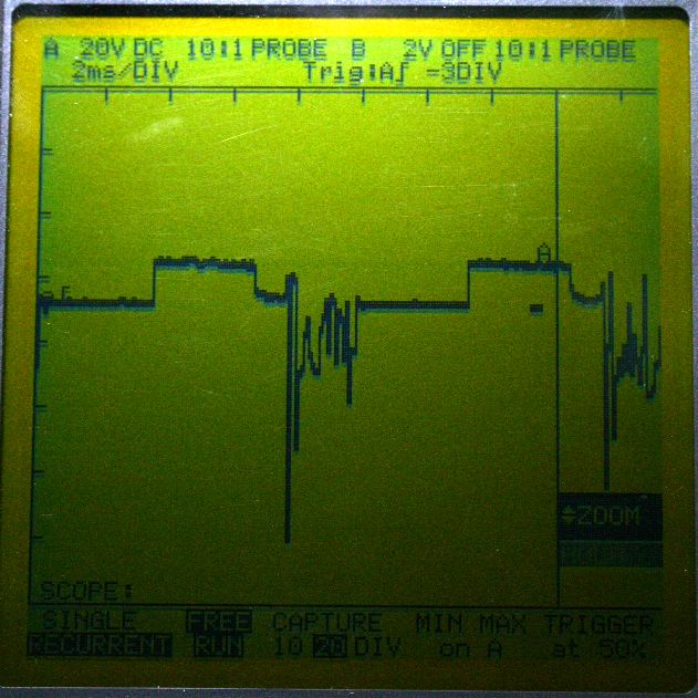 70 volts! Things are getting nasty! The actual voltages could be much higher. The display might be showing the limitations of my instrument. I should note, the ignition unit I'm beating on is of questionable condition. Damien |
|
|
You dream it up....I'll make it
|
|
|
|
|
Dawg
Senior Member
Joined: 15 August 2009 Location: Canada Status: Offline Points: 988 |
Post Options
Quote Reply
Posted: 20 December 2009 at 9:23pm |
|
Here's a picture of the latest batch of heat sinks in case anyone is interested.
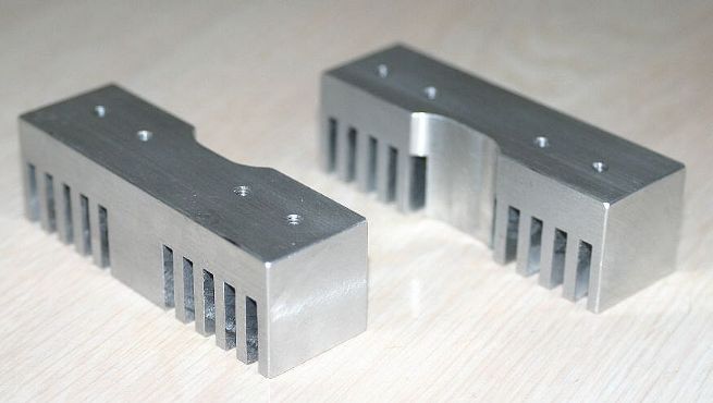 Got a few left, don't know when I'll be making more. Thanks. Damien |
|
|
You dream it up....I'll make it
|
|
|
|
|
Capt Fiero
Admin Group
Founding Member Joined: 12 February 2007 Location: Canada Status: Offline Points: 4039 |
Post Options
Quote Reply
Posted: 22 December 2009 at 8:08am |
|
Damien when you get a chance, I'd love to see what your timing does on a timing light now. You new mag system might solve a 2nd problem that most Fiero's have, however I would have to look at in person to see if it does.
|
|
|
Capt Fiero
88 Fiero GT 5spd V6 Eight Fifty Seven GT V8 5spd. |
|
|
|
|
CFoss
Senior Member

Joined: 13 February 2007 Location: Canada Status: Offline Points: 580 |
Post Options
Quote Reply
Posted: 22 December 2009 at 10:20am |
|
How is this probe hooked up?...bottom of the coil to common(Ground)? It looks like that's it. I would like to see ch1 across the coil, and ch2 hooked to a current probe (.01ohm maybe, 5A = 50mV signal at max) in the primary to show primary charging current...that would nail it.
I think this module is suspect. To define what I'm talking about, the period where the waveform is high is when the ig module is open circuit. When the voltage is low, but not 0 the current is building in the coil and the module is conducting. The small voltage is due to the saturation voltage of the transistors in the module. Then, the negative going spike is when the energy in the coil primary is transfered to the secondary and a spark occurs.
Now, look at the timing...When it's cold, is it open circuit for 4ms, then charging for 5ms or so (This is the dwell on a points system, btw), then it discharges to the plug over 1-2ms period. Good stuff.
Now look at the last one, the ugly. It's o/c for about the same period, then charging for a very short period of time...1ms or so. This causes a dramatic reduction in spark energy, because the coil only has 1/5 the time to build up energy. The current builds linearly, so 1/5 the current, but the enery is proportionl to the square of the current, so something like 4% of the previous energy is delivered. Not good, and it shows in the discharge waveform, which is very low amplitude and I suspect the spikes are due to multiple crappy arcs.
The dwell is supposed to be fixed in this system...ie, the module is shot.
It probably is not strong enough to deliver a signal to a timing light.
Chay |
|
|
86 SE 3.4
|
|
|
|
|
CFoss
Senior Member
Joined: 13 February 2007 Location: Canada Status: Offline Points: 580 |
Post Options
Quote Reply
Posted: 22 December 2009 at 10:30am |
|
I was wrong about dwell being fixed...it is controlled dynamically from the ecm...
So, were these screen shot taken at abou the same rpm? Looks close from my count...9ms vs about 9 ms period, so about 2222rpm?
Am I close?
Chay |
|
|
86 SE 3.4
|
|
|
|
|
CFoss
Senior Member
Joined: 13 February 2007 Location: Canada Status: Offline Points: 580 |
Post Options
Quote Reply
Posted: 22 December 2009 at 10:54am |
|
I read some more via megasquirt, and their typical values for dwell are 2-4ms, depending on the L of the coil used.
For us, if we assume a spark discharge time of 3ms, and dwell of 4ms (Each of these is conservative) we have a total system time of 7ms for each spark. We should be able to maintain this until: 7ms*3sparks/rev = 21ms, 21ms^-1*60 = 2857rpm, at which point the ecm would lower the dwell and the resulting spark time in order to keep it firing on time. So, we get a really good spark at up to 2800rpm, then by 3000rpm, the spark energy is about 1/4 of what it was at 2800 (Because the dwell is /2).
Chay |
|
|
86 SE 3.4
|
|
|
|
|
CFoss
Senior Member
Joined: 13 February 2007 Location: Canada Status: Offline Points: 580 |
Post Options
Quote Reply
Posted: 22 December 2009 at 10:57am |
|
I keep posting, but I realize this suggests something.
If you need better high rpm energy, get a coil with less L and more secondary windings. This will respond better to lower dwells at higer rpm, but will deliver a lower energy spark at sub 2800rpm.
My guess is this is what the MSD blaster is all about.
Chay |
|
|
86 SE 3.4
|
|
|
|
|
CFoss
Senior Member
Joined: 13 February 2007 Location: Canada Status: Offline Points: 580 |
Post Options
Quote Reply
Posted: 22 December 2009 at 1:38pm |
|
Oh, yeah, one MORE thing. The amplitude of the reverse voltage on the coil primary will be equal to the spark plug breakdown voltage*ratio of the ignition coil. Essentially, the ignition coil becomes a transformer, with the primary and secondary "disconnected". Therefore the voltage will build on the primary and secondary until one or the other exceeds the voltage level required to drive current...it lets go on the secondary when the spark plug fires.
This means that there is no good way of reducing this spike, because in doing so you'll be absorbing energy which ought to go to the spark plug. The focus should be on attaining a good dwell time, so the spark plug fires once strongly rather than the weak restrike I see in the last of your scope shots. Comments? Chay |
|
|
86 SE 3.4
|
|
|
|
|
Dawg
Senior Member
Joined: 15 August 2009 Location: Canada Status: Offline Points: 988 |
Post Options
Quote Reply
Posted: 23 December 2009 at 11:38pm |
|
The probe was connected across the two wires coming from the ignition module. So positive 12vdc and the module's pulsing ground. A function generator is triggering the ignition module as a substitute for the pickup coil and there is no ECM, dwell should have been constant. So actually, the high readings are showing the module conducting (closed). As I understand it, this is when the primaries are charging. Somewhere in there the spark should occur....no? If this is so, then the negative going spike is a reflection after the fact. If I get some time after Christmas, I'll see if I can find something to use as a shunt as I have no current probe.
|
|
|
You dream it up....I'll make it
|
|
|
|
|
CFoss
Senior Member
Joined: 13 February 2007 Location: Canada Status: Offline Points: 580 |
Post Options
Quote Reply
Posted: 25 December 2009 at 1:56pm |
|
I have to try this myself. I thought I had it all figured out, and the change in probe position has thrown me into confusion. I don't get how it works, but I'll try to figure it out with the new info.
Chay |
|
|
86 SE 3.4
|
|
|
|
|
Patrick
Newbie 
Joined: 19 April 2008 Location: Vancouver Status: Offline Points: 5 |
Post Options
Quote Reply
Posted: 26 December 2009 at 12:21pm |
|
That makes (at least) two of us. Seems as though there's plenty of discussion on this topic... Here.
|
|
|
|
|
CFoss
Senior Member
Joined: 13 February 2007 Location: Canada Status: Offline Points: 580 |
Post Options
Quote Reply
Posted: 26 December 2009 at 5:30pm |
|
I have a new thought which seems to fit. You can confirm it with the current probe.
The high voltage corresponds to the dwell. The dwell is long enough that the maximum peak current is reached. This is a module maximum current and protects the module and stops the coil from overheating. The value increased through the years. It started at 5 amps and unded up at 8 amps. I'm not sure where ours fit in. Anyway, when the max current is reached, the voltage across the coil drops to the value required to maintain the current flow which is quite low because the only factor is the parisitic resistance in the coil primary. This drop from high voltage to low slightly positive voltage should be coincident with the ramping current leveling off. Then sometime later, the module interrupts the current flow and the large reverse voltage is the reflected voltage required to fire the plug on the secondary. As the frequency increases, the amount of 'max current' time should decrease until it dissapears. Then the voltage should go from the positive directly to the negative with no intermediate level. I'd be interested in the results of the I probe. It should be quite reveling. I haven't had a chance to read the link. I'll do it when I get a chance. C |
|
|
86 SE 3.4
|
|
|
|
|
Dr.Fiero
Senior Post God

Joined: 12 February 2007 Location: Canada Status: Offline Points: 1726 |
Post Options
Quote Reply
Posted: 26 December 2009 at 5:57pm |
|
I have a low amp clamp probe you can borrow.
|
|
|
|
|
CFoss
Senior Member
Joined: 13 February 2007 Location: Canada Status: Offline Points: 580 |
Post Options
Quote Reply
Posted: 26 December 2009 at 10:04pm |
|
The clamps might work if it was the right type. All the current to voltage types I've used add delay, so they would show the waveform correctly, but it would not allign to make sense with the voltage waveform and be conclusive. The best way to go is a good old resistor...the trouble is breaking it into the circuit of course.
Chay |
|
|
86 SE 3.4
|
|
|
|
|
Capt Fiero
Admin Group
Founding Member Joined: 12 February 2007 Location: Canada Status: Offline Points: 4039 |
Post Options
Quote Reply
Posted: 03 January 2010 at 12:14am |
|
Damian, when you do sell one, make sure to get the buyer to keep a report on how well it works. Another interesting test would be to take some "bad" modules or pickup coils, and test them in your fancy device and see if the bad parts come back to life. |
|
|
Capt Fiero
88 Fiero GT 5spd V6 Eight Fifty Seven GT V8 5spd. |
|
|
|
|
Dawg
Senior Member
Joined: 15 August 2009 Location: Canada Status: Offline Points: 988 |
Post Options
Quote Reply
Posted: 03 January 2010 at 7:08pm |
|
Well the exact same setup is in Michelle's daily driver. Other than that connector issue, it's been working perfectly. If a problem of any kind pops up I will report it.
As far as testing goes. It's going to take a while before I know exactly what good and bad really are. If anyone wants to bring me their suspected dead or old modules so I can beat on them that would be good. Eventually, I will learn how to tell what shape they're in.
|
|
|
You dream it up....I'll make it
|
|
|
|
|
Post Reply
|
Page <1234> |
 Tweet
Tweet
|
| Forum Jump | Forum Permissions You cannot post new topics in this forum You cannot reply to topics in this forum You cannot delete your posts in this forum You cannot edit your posts in this forum You cannot create polls in this forum You cannot vote in polls in this forum |


 Topic Options
 Capt Fiero wrote: